
We’ve added AI-assisted modeling and analysis to Nodi.
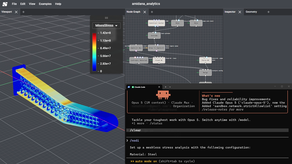
Drive your Nodi node graph directly from the AI agent you already use — Claude Code, Cursor, or Codex — placing nodes, wiring them up, and tuning parameters.
This article covers the thinking behind the feature and three concrete ways to use it.
Where “AI CAD” Stands Today
AI-driven modeling tools have proliferated over the past few years. The approaches vary, but it helps to sort them into three broad families.
- Embedding an assistant into existing CAD (e.g. Autodesk Fusion)
- Text to CAD — generating geometry from a prompt (e.g. Zoo (formerly KittyCAD), AdamCAD)
- Code CAD — write it as code, and let agents write it (e.g. ForgeCAD)
That said, many Text to CAD tools are built around a code representation internally (KCL for Zoo, OpenSCAD for AdamCAD) — so they can be seen as Code CAD with a polished GUI on top.
The Shared Promise, and the Shared Walls
The expectation behind all three families is the same: let AI handle the tedious parts of modeling. In practice, though, you tend to run into two walls.
- Humans and AI can’t easily work together: work ends up trapped inside an AI-only chat UI or file format, making it hard to move back and forth with your existing modeling work. A shape does come out, but it’s assembled in a way that’s hard to edit, so you can’t tell where to make a change and end up rebuilding it just to fine-tune
- Setup is heavy: configuring MCP servers, managing API keys, installing plugins — a lot of steps before you get to model anything
The first one in particular surfaces across families. In each case, “what the AI produced” and “what the human normally touches” end up being different things — the same shape of problem.
Nodi’s AI assistance takes these two points as its starting design constraints, and pursues something close to the third family’s thinking — but on a node graph rather than code. A node graph, like code, is an explicitly structured and editable representation, yet you can manipulate it directly in a GUI: a format an AI can read and write, and a human can edit by hand as usual.
Nodi’s Approach
1. It Works Inside Your Existing Workflow
Everything the agent does is exactly the same node adding, wiring, and parameter editing you’d do by hand.
Its edits appear on the canvas live, so you can pick up where it left off — or hand off just one part of a graph you built yourself.
- Works on existing projects: no need to start a new file; you give instructions against the project you already have open
- The result stays a node graph: what gets generated is not the geometric data that makes up the shape itself, but the structure of nodes that produces it — so you can walk back through the nodes and adjust anything you don’t like
- Undo works: if you don’t like a change, revert it like any other edit
The goal isn’t to hand modeling off wholesale — it’s to let manual work and AI move back and forth on the same canvas.
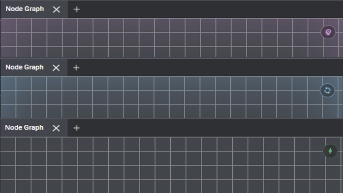
2. Node Graph Output Means You Can Verify It — and Split the Work
The agent doesn’t guess node names or port layouts — it looks them up in Nodi’s node catalog before building the graph. After editing, it evaluates the graph and checks the resulting geometry before deciding what to do next.
Because the output is a node graph, you can trace which node produces which part of the shape. When the result isn’t what you intended, you fix that one spot instead of rebuilding.
3. No MCP Server Configuration
The Nodi desktop app starts a local control server automatically on launch.
The AI agent drives Nodi by sending commands to that server through a CLI.
That means you never add an MCP server entry to a config file or start a server process yourself. Setup is a single command, run once in your terminal:
npx @nodi3d/agent@latest setupThis installs Nodi’s agent skills into your AI agent (Claude Code, Cursor, Codex, and others).
From there, running /nodi in your agent connects it to the project open in the desktop app.
The install prompt is published here.
Use Case 1: Modeling from Photos and 2D Images
You can hand the agent reference images and have it build the shape as a model — photos, renders, technical drawings, or spec sheets all work.
The agent reads dimensions and structural elements out of the images, writes up a shape brief, builds a graph per part, and takes screenshots at each stage to compare against the references as it refines the form.
For example:
Recreate the beam part of the hanging shelf in this drawing [image attached]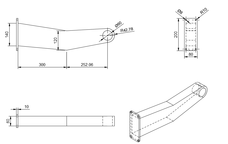
Filling in dimensions the image can’t convey improves accuracy. When you can hand over a drawing or spec sheet instead, the agent pulls the dimensions from there.
As noted, what you end up with is a node graph. Changes like “make the plate 5mm” or “change the hole pitch” can be given to the agent as a follow-up, or made by hand on the corresponding parameter.
Use Case 2: Writing Expressions
Nodi has two kinds of nodes for writing values or geometry directly as a script.
- Expression / Function nodes: generate values and point lists in Rhai, with vector and point types like
vec3andpt3, plus noise and interpolation functions available out of the box - Implicit Expression nodes: write the implicit function (SDF) itself in WGSL, the GPU shader language. By writing a function that returns the signed distance at any point in space, you define shapes that are awkward to express by combining nodes
The agent can write both of these for you from natural language.
Formula-driven shape generation is often faster to write as an expression than to wire up as nodes — but it’s also where you stall trying to recall syntax or fix an off-by-one in an index. That’s exactly where an AI agent helps.
Example: A Tapering Helix of Points
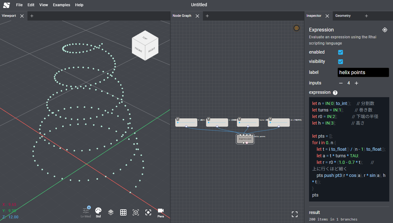
Ask for “a helix of points that tapers as it goes up,” and you get an Expression node holding something like this:
let n = IN[0].to_int();     // segment count
let turns = IN[1];          // number of turns
let r0 = IN[2];             // radius at the base
let h = IN[3];              // height

let pts = [];
for i in 0..n {
    let t = i.to_float() / (n - 1).to_float();
    let a = t * turns * TAU;
    let r = r0 * (1.0 - 0.7 * t);       // narrows toward the top
    pts.push(pt3(r * cos(a), r * sin(a), h * t));
}
pts
Example: A TPMS Lattice with Position-Varying Thickness
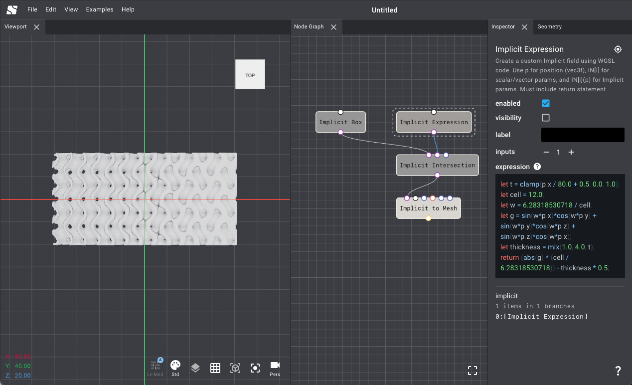
The second example uses an Implicit Expression node, written in WGSL.
Ask for “a Gyroid that gets thicker as it goes along X,” and you get something like this:
let t = clamp(p.x / 80.0 + 0.5, 0.0, 1.0);   // normalize X position to 0..1
let cell = 12.0;                              // unit cell size
let w = 6.28318530718 / cell;

// trigonometric form of the Gyroid
let g = sin(w * p.x) * cos(w * p.y)
      + sin(w * p.y) * cos(w * p.z)
      + sin(w * p.z) * cos(w * p.x);

let thickness = mix(1.0, 4.0, t);             // varies continuously from 1mm to 4mm

return (abs(g) * (cell / 6.28318530718)) - thickness * 0.5;
This kind of “vary the property by location” description comes up constantly in DfAM, yet it gets unwieldy when built purely from node combinations. Writing it as a single expression keeps it legible — and makes it a good fit for an agent to write.
Nodi also ships an ImplicitTPMS node (covering six TPMS types including Gyroid, SchwarzP, and Diamond)
and an ImplicitRamp node that drives thickness from a field value such as stress,
so standard lattices can be built from nodes alone.
The agent can make the call on which approach fits, too.
The generated script stays inside the node, so tweaking coefficients or adding a branch is ordinary editor work you do whenever you want.
Use Case 3: Sending the Model Straight into Analysis
The Nodi desktop app can run analysis (CAE) on a modeled shape directly from the node editor. It uses meshless analysis (Immersed FEM), which embeds the shape as an SDF into a background structured grid, so there’s no meshing step for the user. We covered this in a separate article.
Removing meshing as a manual bottleneck also means analysis becomes one continuous operation for the agent as well.
In other words, the loop of “build a shape → analyze it → look at the result → adjust the shape” is something you can hand to the agent as-is.
For example:
Fix the four corner holes (Φ8mm) of this beam part, apply a 1000N downward load
to the Φ60mm hole, and run a structural analysis
With conventional CAE, every shape change means re-meshing, which makes running this loop quickly difficult in itself. Combining meshless analysis with an AI agent shortens that design loop substantially.
Summary
We introduced Nodi’s AI-assisted modeling.
- Fits your existing workflow: the agent’s actions are the same node edits you’d make by hand, the result stays a node graph, and you can adjust it directly
- No MCP configuration: the desktop app starts the control server itself, so setup is a single command
- Modeling from images, Expression generation, and analysis: delegate the tedious parts while keeping design decisions in your hands
The aim isn’t to hand modeling off to AI wholesale — it’s to make AI something you can reach for selectively within your normal modeling work.
This feature is available in the Nodi desktop app. If you’re interested, please join the waitlist. We welcome feedback and collaboration inquiries.